


IPFS News Link • Gun Rights
AR-15 Lower Receiver
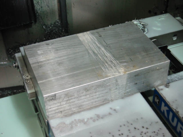
• ww.cncguns.comThe AR-15 lower receiver was the first project that I started. I got the idea when I saw the lower receiver forging that Pvt. Ryan at Roderus Custom Gunworks was working on. He started with a raw forging, which is basically a block of aluminum, but in the shape of lower receiver. He done a great job of showing all the details of his work. That got me thinking that I could do the same thing with CNC (Computerized Numerical Control) equipment. But instead of starting with a forging, I thought I wanted more of a challenge so I started with a block (billet) of aluminum. After I found the solid model file for the AR-15 lower receiver, I knew what I wanted to do could be done. I spent many hours coming up with a game plan of how I was going to machine the lower receiver. After I had my game plan together, I started programming the lower receiver using a type of computer software called CAM (Computer Aided Machining). CAM is often used along with CAD (Computer Aided Design) and this process is called CAD/CAM. Since I already had the solid model of the lower receiver (the CAD part), all that was left was the CAM. After I programmed all the tool paths that I wanted the CNC machine to make, I sent the program out to the machining center. I cut the 5x2 billets of aluminum, and I was almost ready to start doing some cutting.
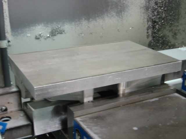
Here is what the lower receiver looked like at the start of the 1st operation...
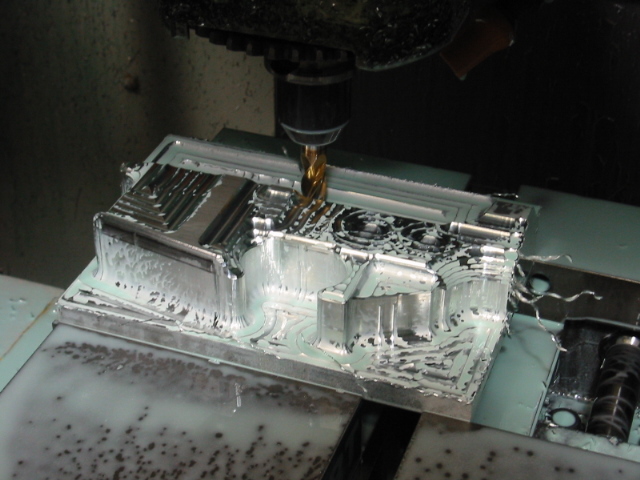
Here you can see the 1/2" carbide ball nose endmill roughing the profile. You can tell that it's already starting to look like a lower receiver...
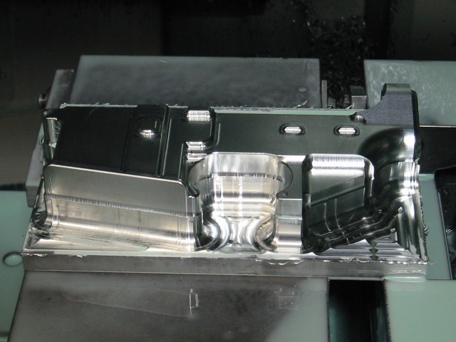
After the profile was roughed, I then made a finish pass with a 1/4" carbide ball nose endmill. I started at one end of the receiver and machined across the whole profile stepping over 0.004" each time. So as you can imagine this process takes a really long time. If you had a part that was 7" long, and using a 0.004" step over, it would have to make 1,750 passes. Machining the receiver the way I did wasn't the most cost effective way, but I wasn't real worried about time, since this was my new hobby. Here you can see what the receiver looked like after the finish profiling pass...
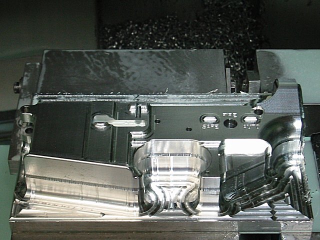
The next step was to do all the detail machining and drilling the holes. I also engraved on the side of the receiver. You will see that I engraved AUTO, but this is strictly for looks!!! Since I don't want to spend any time in prison, I never have and never will make any full auto weapons. Here's what it looked like after the 1st operation...
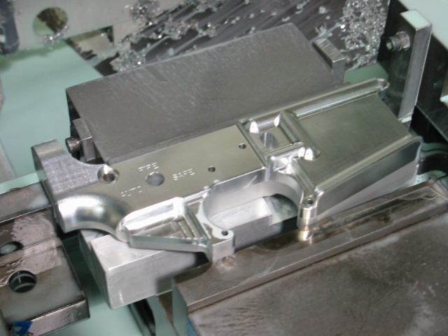
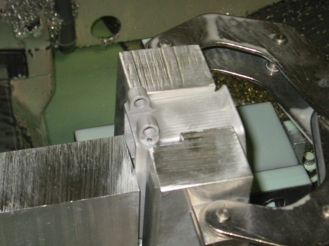
For the 2nd operation, I flipped the receiver over and machined the other side to remove the big slab of material. Here you can see what it looked like at the start of the 2nd operation...
In order to hold the receiver flat and square, I had to design a setup block that the receiver could set on while it was in the vice. In this picture you can see what the early setup blocks looked like, the current setup blocks are much more advance than this early version...
Here you can see how I made a rough pass around the outside of the receiver to remove most of the extra material...
This picture is after I used the 3" shell mill to flycut the receiver down to the correct thickness, and then used a carbide endmill to contour around the outside...
I had to make the same rough and finish profiling passes as I did on the 1st operation. I also engraved on this side of the receiver as well...
At this point I'm able to slide the pistol grip on the receiver a little ways...
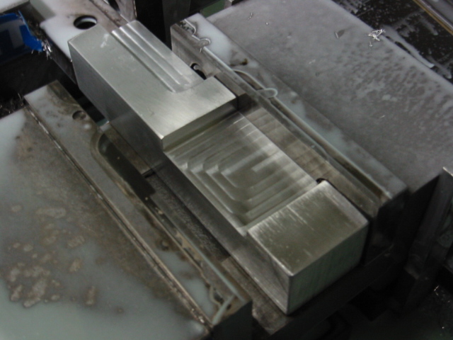
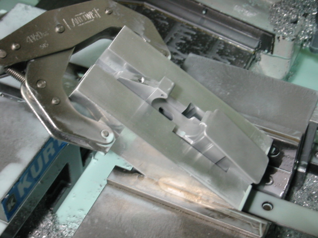
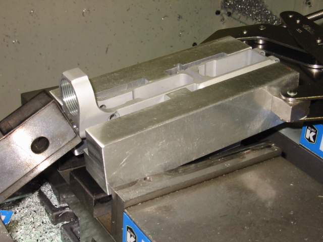
For the 3rd operation I machined the fire control area and the part of the magazine (mag) well. Since the mag well is so deep, I couldn't get an endmill down to the full depth, so I decided to machine part of the mag well from the top side and finish machining it from the bottom side. Since the endmill will leave a radius in the corner, I will have to go back and use a file to file out the corners so a mag can slide in. Most companies use a wire EDM (Electrical Discharge Machine), or a broach to complete the mag well, but since I didn't have access to these types of tooling, I had to just machine the mag well, and finish it with a file. The next time I made these receivers I drilled the corners out with a small drill bit. This saved alot of time since I didn't have to file so much material out, but for some reason I didn't think about this the first time I made the receivers. The pic below is the setup I used for the 3rd operation, notice the setup blocks I made for both sides of the receiver to hold it flat and square...
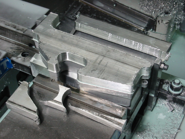
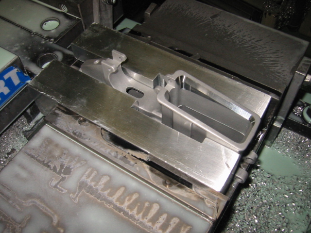
This is what the receiver looked like after the machining was finished...

After the 3rd operation was finished, I was able to see if some of the fire control parts would fit. Come to find out, everything fit perfectly...
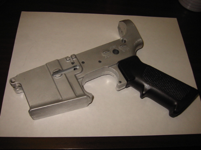
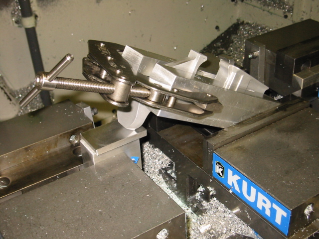
On the 4th operation I decided to drill the pistol grip hole. I done this hole next, because I knew there was still enough material left inside the receiver that it wouldn't bend when I clamped it into the vice. I used a C-clamp to help hold the blocks against the receiver, and to make everything more stable. Notice the blocks I used to support the buffer tower. These blocks gave me the correct angle so the pistol grip hole could be done in the exact location...
Here is a pic after the hole was drilled and tapped for the pistol grip...
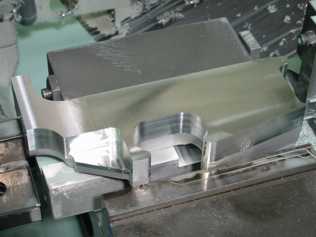
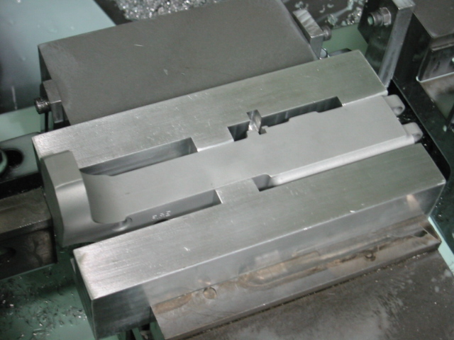
For the 5th operation I machined the bottom of the receiver. You will notice that I once again used the setup blocks. The setup blocks ended up being a very useful piece of tooling...
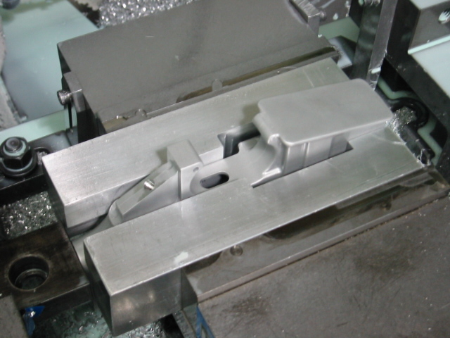
Here you can see what the receiver looked like after the 5th operation. Notice the chamfer around the mag well. I machined that using 3-d profiling. It was much easier for me to profile that chamfer instead of trying to use an angled endmill to contour around the mag well. You can see how the cut from the top side of the mag well matched up with the bottom cut. It matched up much better than what the picture shows...
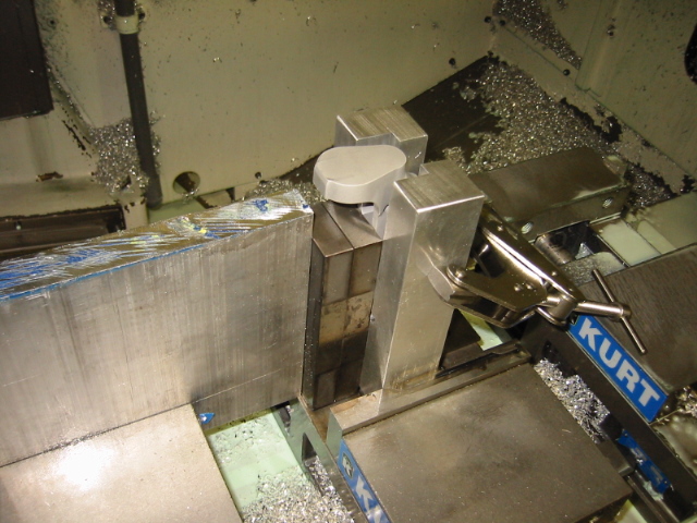
The 6th operation I machined the buffer hole. Most people use a drill / reamer / and tap for this hole, but since I was doing this on a CNC machine, I went with just milling the hole and then using a thread mill to cut the threads. A thread mill is just like an endmill in that it contours the hole, but as it's going around the hole, it's also going down, so all 3 axes of the CNC machine is moving at the same time. Machining the threads in this fashion leaves great looking threads. Here you can see the setup that I used...
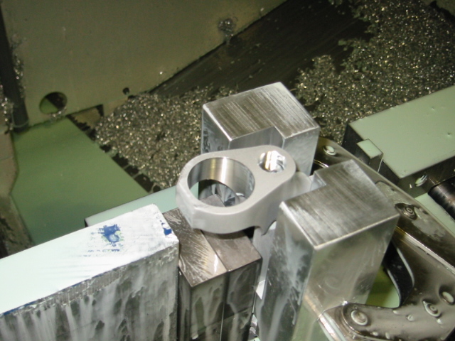
This is a picture after the hole was contoured with a endmill and ready to be tapped...
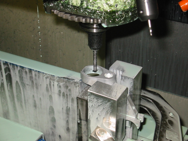
Here is a picture of the thread mill cutting the threads...
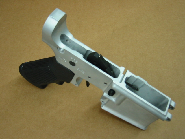
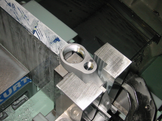
And here is what the receiver looked like after the buffer was threaded and the hole for the detent was drilled...
For the 7th operation I drilled the front detent hole. The setup for this operation was basically the same as the buffer hole setup...
For the 8th operation I drilled the hole that keeps the buffer spring held back. This isn't a very good pic of the hole, but maybe you can get an idea of how this operation was setup...
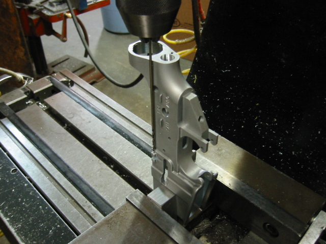
The 9th operation is the last operation. This operation I drilled the bolt catch hole. A 6" long aircraft extension drill is needed for this hole. I was scared to do this operation on the CNC. So I ended up putting it on a manual mill. This would allow me to guide the drill bit in the correct location. The drill has a small diameter and is very long, so it would be very easy for the drill to just "walk" off. I later designed a bolt stop fixture that would guide the drill bit in the exact location, I could even do this hole with just a cordless drill. After I designed the new style setup blocks, I incorporated this bolt stop fixture in the blocks. Here you can see how I drilled this hole without any special tooling...
Watch Streaming Broadcast Live:
LRN.fm
DLive

Telegram